สายพานพื้นผิวเรียบ
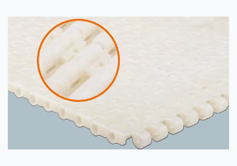
Closed conveying faces for stable support, packaging transfers and straight-running duties where through-belt drainage is not the main requirement.
EVER POWER supplies plastic modular belt configurations, conveyor accessories and related plastic chains for OEM, system-integration and replacement projects. Selection is organised around measurable conveyor variables rather than unsupported model assumptions.

A plastic modular belt is a positive-drive conveying surface built from linked modules. Its practical value comes from how the modular geometry, face pattern and sprockets work together around the product and conveyor layout. For a new design, start with the process. For replacement work, start with measurable geometry.
The most useful first questions are simple: Is the belt straight-running or side-flexing? What is the smallest product footprint? Does water or air need to pass through? How tight are the transfers? What belt pitch and width are required? What sprocket and shaft interface already exists? Answering those questions narrows the range before material, documentation and accessory details are confirmed.
| Selection input | What it changes |
|---|---|
| เส้นทางวิ่ง | Straight family or radius/side-flexing geometry |
| Product footprint | Required support and acceptable opening pattern |
| Process condition | Drainage, airflow, release and cleaning needs |
| Transfer size | Pitch and edge/hinge geometry |
| Drive interface | Sprocket family, tooth engagement, bore/shaft and spacing |
| Project documents | Material, drawing or inspection requirements for the ordered configuration |
Closed conveying faces for stable support, packaging transfers and straight-running duties where through-belt drainage is not the main requirement.
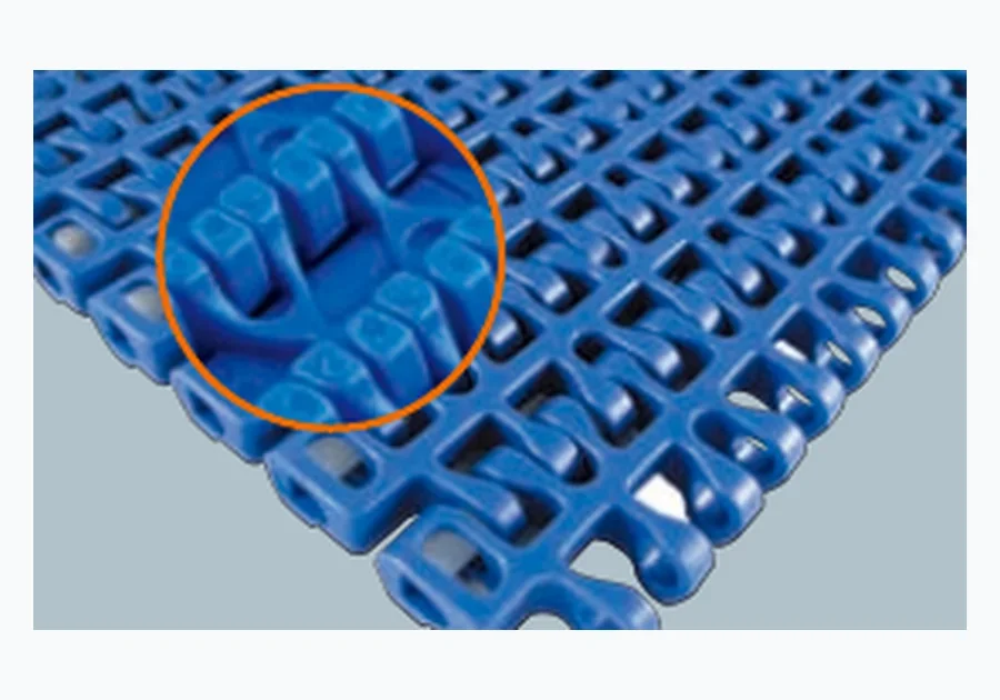
Open-area configurations for washing, drainage and airflow. Selection should still check the smallest product footprint and transfer geometry.

Side-flexing modular geometries for horizontal curves and compact layouts. Inside radius, belt width, guide path and drive position must be reviewed together.
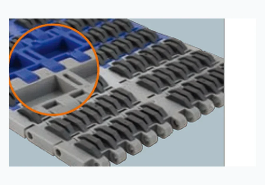
Duty-specific faces for applications that need a different balance of support, opening, release or conveying behaviour than standard flat or open-grid surfaces.
The comparison range spans several pitch and opening levels. That does not mean every face is available at every pitch. Use the matrix below to see the reference combinations, then confirm the final width, material, drive and operating limits for the ordered configuration.
| Pitch | Surface direction | Open area reference | Path |
|---|---|---|---|
| 12.7 mm | Flat / closed | Not specified | Straight |
| 15.2 mm | Flat / closed | Not specified | Straight |
| 15.2 mm | Open grid | 14% or 28% | Straight |
| 19.05 mm | Flat / closed | Not specified | Straight |
| 19.05 mm | Open grid | 16% | Straight |
| 25 mm | Flat / closed | Not specified | Straight |
| 25 mm | Open grid | 29% | Straight |
| 25.4 mm | Flat / closed | Not specified | Straight |
| 25.4 mm | Open grid | 34% or 35% | Straight |
| 25.4 mm | Specialty / partially open | 8% on one configuration | Straight |
| 27.2 mm | Open grid | 38% | Straight |
| 50.8 mm | Flat and specialty/open | 20% on one configuration | Straight |
| 63.5 mm | Flat / closed | Not specified | Straight |
| 25 mm | Radius / side-flexing | 52% | Radius |
| 25.4 mm | Radius / side-flexing | 47% or 55% | Radius |
Use a flat or closed face when stable support is the dominant requirement: cartons, totes, containers, trays, small components and many dry packaging transfers. Use an open-grid face when the process needs water, air or debris to pass through the conveying surface.
The comparison is not binary. A line can wash product on an open belt, inspect it on a closer surface and pack it on a flat belt. The correct decision belongs to each conveyor section. Open-area percentage is useful, but the actual hole pattern and the product footprint should be reviewed together.
| Decision | Flat / closed | Open grid |
|---|---|---|
| Product support | Continuous support; useful for smaller bases | Check how the smallest item bridges openings |
| Drainage | Limited through-belt drainage | Through-belt drainage is a primary benefit |
| Airflow/cooling | Limited through-belt airflow | Can improve through-belt airflow |
| Fine transfer | Often a strong starting point | Confirm edge/opening geometry |
| Debris release | Debris stays on the face unless removed | Openings can allow debris to leave the process zone |
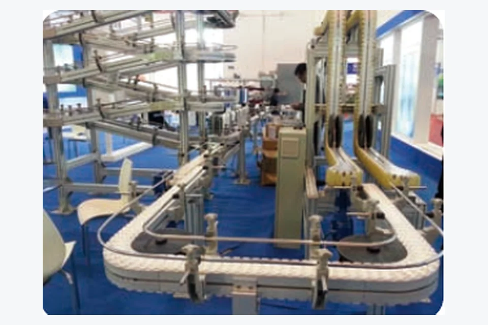
Horizontal curves need a side-flexing belt family. The useful geometry is not defined by pitch alone: belt width, inside radius, turn angle, guide profile and drive location all influence the path. The configuration range includes 25 mm and 25.4 mm radius examples, with 47%, 52% and 55% open-area references.
For a retrofit, send a plan-view sketch and photographs of the inner and outer guide path. If the curve is difficult to measure, provide several fixed frame dimensions so the required radius can be reconstructed during review.
A straight-running belt with the same nominal pitch is not automatically a mechanical substitute for a side-flexing belt.
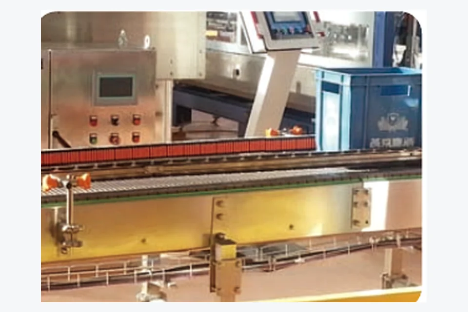
Map each conveyor section by product support, wet/dry condition, cleaning method and transfer size before choosing the face.
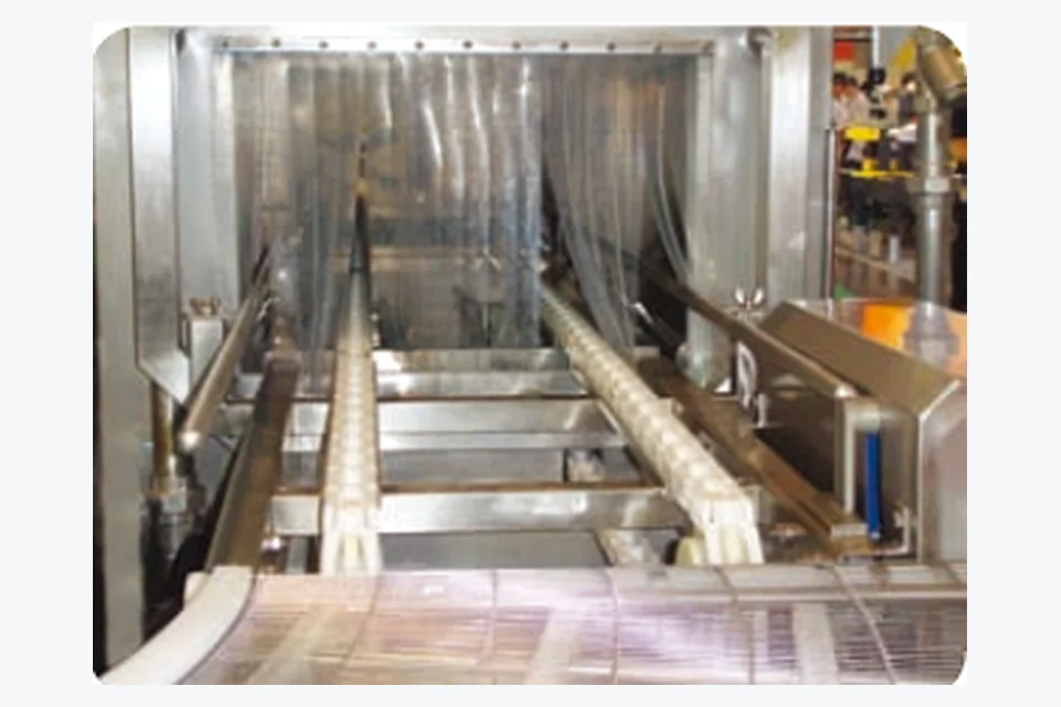
Use open area as a process variable, balancing water release and airflow against the contact footprint of the conveyed product.
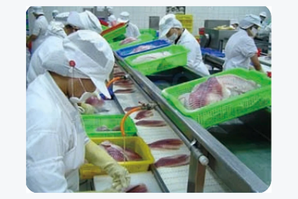
Cold, wet operation and frequent cleaning make drainage, product support and project-specific material documentation important.
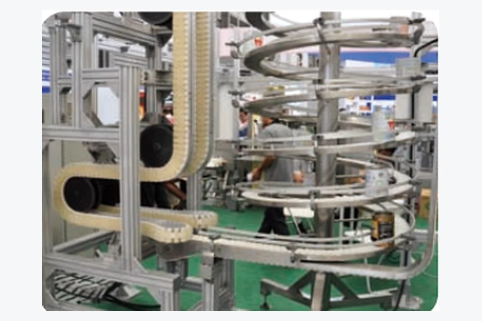
Cooling duty combines airflow with support for warm or soft products; curves and spirals add radius geometry to the selection.
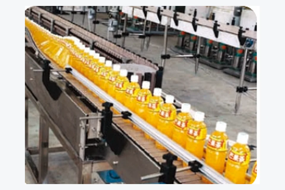
Container base stability, wet zones, guides, accumulation and machine-to-machine transfers drive the useful belt configuration.
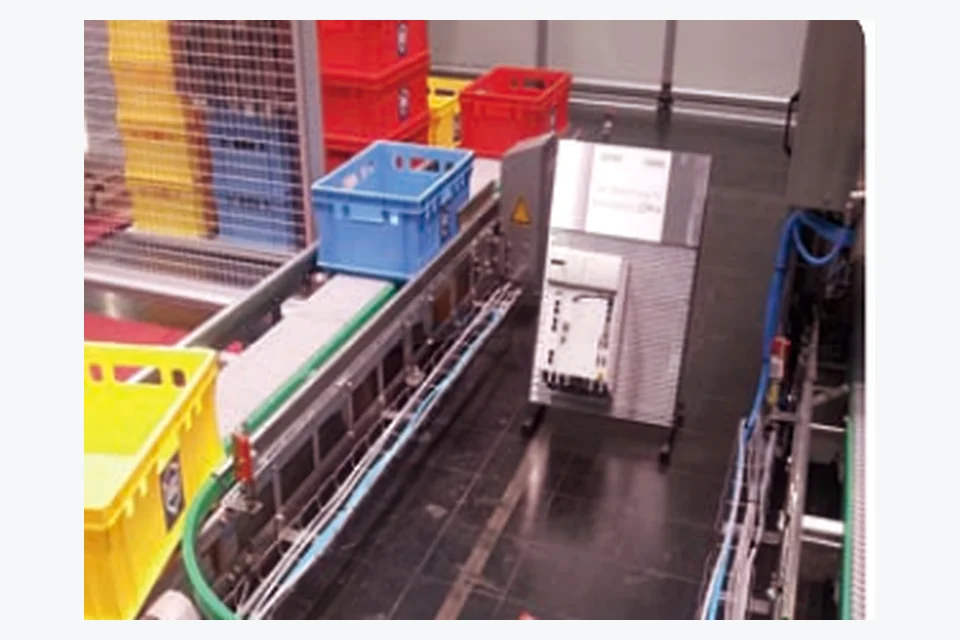
Stable tracking and predictable transfers matter around sensors, case packers, labelers, palletizing cells and tote handling.
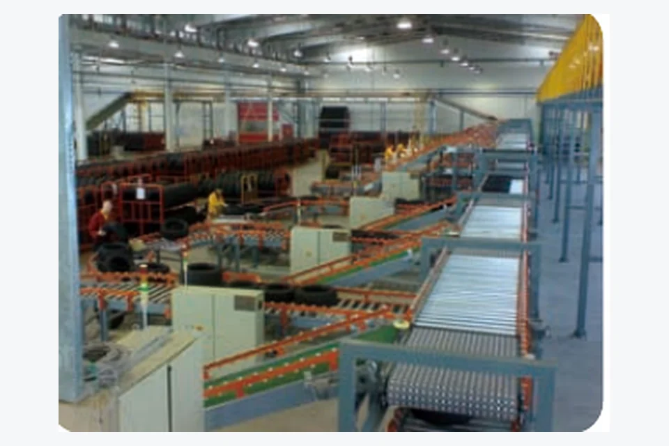
Parcel footprint, transfer gaps, duty cycle and service access matter as much as the nominal belt pitch.
Curve layout is a system geometry question: inside radius, width, guide track, angle and drive position belong in one review.
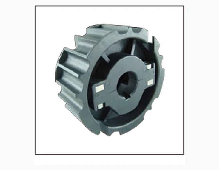
Match belt underside geometry, tooth count, sprocket form and shaft/bore details.

The pin reference range covers approximately Ø2–Ø10 mm with PP, PE, PA and POM material examples.
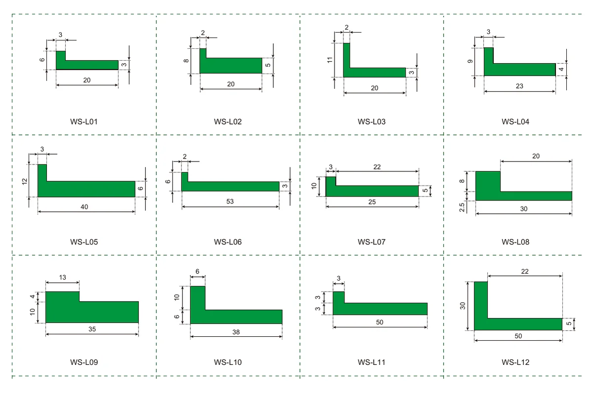
Flat and profiled support sections locate the moving belt/chain in the conveyor frame.
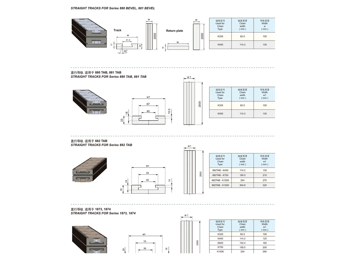
Straight and curved guide/support elements should be specified by function, section and mounting interface.
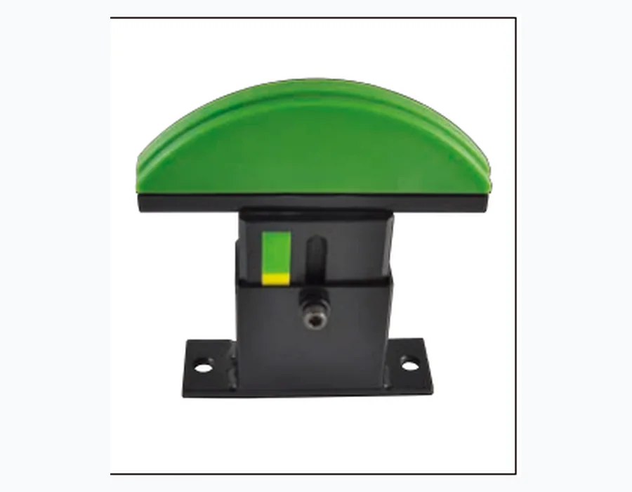
Related chain tensioning references are available for conveyor systems where controlled take-up is required.
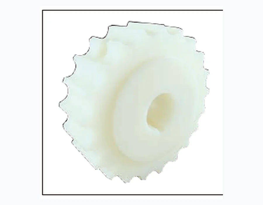
When an old belt code is missing, incomplete or from another naming system, work from measurable mechanical details. Measure pitch across several repeating hinge centres, record belt width, photograph the conveying face and underside, show the hinge/pin detail and photograph a sprocket while it is engaged with the belt. Add the conveyor path and the product being handled.
This approach avoids a common failure: choosing a belt that looks similar from above but has different underside engagement or curve geometry. The same measurement package is useful for comparing replacement accessories such as sprockets, wear strips and guides.
| Replacement check | Send us |
|---|---|
| Belt | Pitch, width, face/open area, hinge/pin and edge details |
| ขับ | Sprocket photo, tooth count if possible, bore/shaft profile and spacing |
| Conveyor | Straight/curve, centre distance, transfer dimensions and guide path |
| หน้าที่ | Product, load, speed, wet/dry condition and cleaning environment |
For new conveyor or machine projects, send the layout you already use internally: PDF, CAD-derived dimensions, a marked-up sketch or photographs. Useful configuration variables include belt width, overall length/centre distance, running path, pitch direction, desired face/opening, sprocket/shaft interface and any related guide or wear-strip profile.
Custom capability should be treated as a configuration review, not an automatic promise. The final belt width, accessory geometry, material and documentation set are confirmed against the requested design and quantity before quotation.
| Check | Buyer value |
|---|---|
| Pitch and repeating geometry | Reduces wrong-family selection |
| Belt width and edge form | Confirms frame and product-clearance fit |
| Pin/hinge condition | Supports assembly and maintenance review |
| Sprocket engagement | Confirms drive-interface direction |
| Guide / wear-strip section | Checks support and tracking interface |
| Material / documentation request | Makes project approval requirements explicit rather than assumed |
Food, beverage, packaging OEM and MRO projects often combine washdown requirements with replacement identification and uptime concerns.
Food technology, seafood and automated production make pitch, open area, radius geometry and useful technical documentation central to selection.
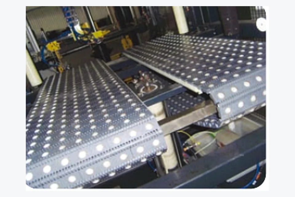
Precision machinery and secondary packaging projects benefit from clear drawings, controlled dimensions and careful interface matching.
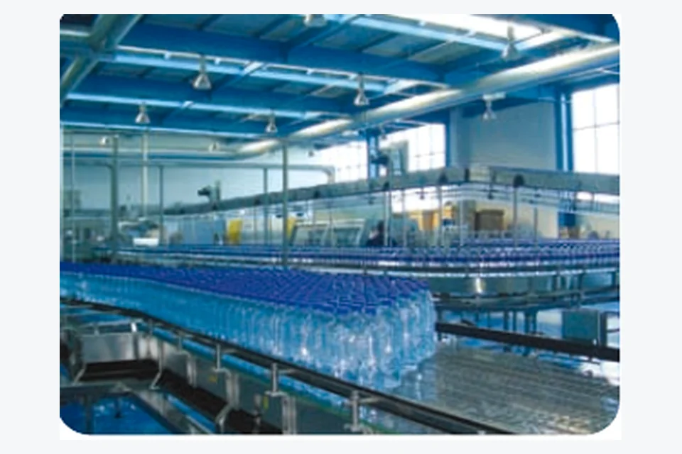
Packaging-machine OEM work puts custom width, transfer geometry, sprocket interface and replacement documentation close to the buying decision.

Produce handling and logistics create two strong but different use cases: wet post-harvest processing and high-cycle parcel/tote transfer.
Compact food, packaging and precision-equipment layouts reward exact dimensions, tight transfer review and traceable product identification.
A step-by-step sequence for application, path, support, pitch and drive interface.
How pitch narrows a family without proving full mechanical compatibility.
Compare support, drainage, airflow and transfer trade-offs.
A measurement-led replacement method for unidentified or legacy belts.
Start with product footprint, transfer geometry and the existing drive interface. Pitch narrows the family but does not define the face or sprocket compatibility by itself.
No. Choose enough opening for the process while keeping the product securely supported on the real grid pattern.
Yes. Pitch, width, top/underside photos, hinge/pin details and sprocket engagement are often more useful than a partial code.
Belt width, inside radius, curve angle, guide arrangement, drive location and product footprint.
Yes. Include tooth count, bore/shaft profile, sprocket spacing and existing drive photographs or drawings.
State the exact material or regulatory documentation required by the project. It must be confirmed for the ordered configuration.
Conveyor plan/side view, belt width, path, transfers, load/speed, desired face, drive interface and quantity/project stage.
Send clear photographs and measurements. A physical sample description plus sprocket information can support a structured replacement review.
A formal drawing is useful, but it is not required to start. Photos, pitch, belt width, conveyor path, conveyed product and sprocket information are enough for an initial configuration review.