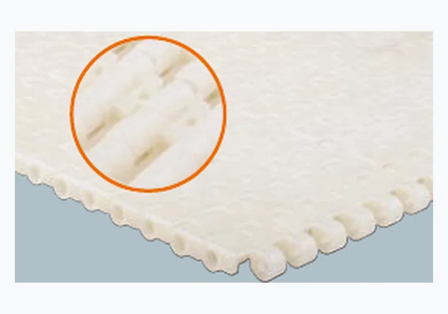
Flat Surface Plastic Modular Belts
Use this family as a selection direction, then confirm the actual pitch, face, width and conveyor interface.
Small machined, moulded or assembled parts can be more sensitive to transfer gaps and local contact than much heavier packages. Selection should focus on the smallest part, the contact face, locating requirements and the machine interfaces around the conveyor.
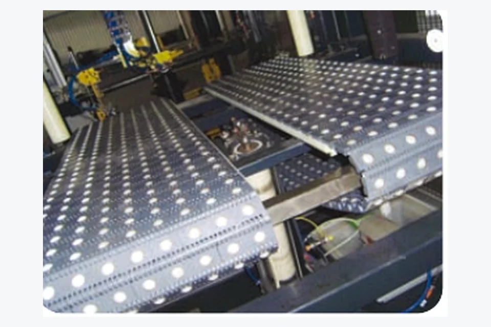
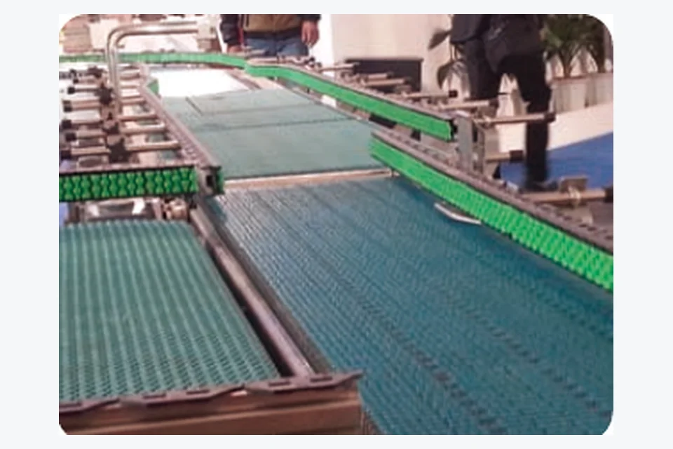
Precision transfer may occur between machining, inspection, washing, assembly or packaging operations. Some sections need a stable closed face; others need drainage or cooling. The useful belt can therefore change with the operation even when the parts are from the same product family.
For Modular Belts for Precision Parts Transfer, the conveyor should be described as a specific process position rather than only by a belt name. That gives a new-design or replacement RFQ enough context to distinguish support, opening, path and drive needs.
| Input | What to describe |
|---|---|
| Part size | Smallest dimensions and centre of gravity |
| Contact sensitivity | Marking, scratching or edge damage concerns |
| Transfer | Smallest gap and required orientation |
| Process | Dry transfer, washing, cooling or inspection |
| Automation | Fixtures, sensors, robots or indexing stops |
| Cleanliness | Debris control and cleaning method |
Small parts can enter openings, tilt at transfers or lose orientation at a guide. Surface details can also mark cosmetic parts. These issues are often solved by geometry and interface design before any special material is considered.
For Modular Belts for Precision Parts Transfer, solve product support, process opening, conveyor path and drive compatibility first. Material and project documentation can then be confirmed for the selected configuration.
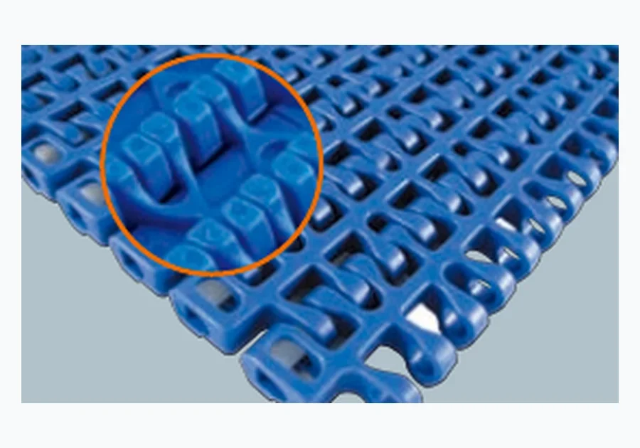
Fine-pitch flat surfaces are a useful starting point for tight transfers and small footprints. Open-grid options can be considered where parts must drain or cool, provided the opening pattern still supports the part securely.
The comparison range includes 12.7 and 15.2 mm fine-pitch references, useful when compact transfer is important. The actual underside and sprocket geometry must still match the conveyor.
If drainage or airflow is needed, compare the smallest part against the grid pattern. Percentage opening alone cannot show whether a corner, pin or small feature will catch.
Compact automated equipment sometimes uses curves to save floor space. When it does, switch the evaluation to a radius family and include belt width and guide geometry.
| Curve input | Why it matters |
|---|---|
| Belt width | Radius capability is related to the selected family and width |
| Inside radius | Defines the turn requirement |
| Curve angle | Sets total path through the guide system |
| Guide profile | Controls location and wear through the curve |
| Drive position | Changes how the belt enters/leaves the curve |
| Product footprint | Checks stability and support through the turn |
Use this family as a selection direction, then confirm the actual pitch, face, width and conveyor interface.
Use this family as a selection direction, then confirm the actual pitch, face, width and conveyor interface.

Use this family as a selection direction, then confirm the actual pitch, face, width and conveyor interface.
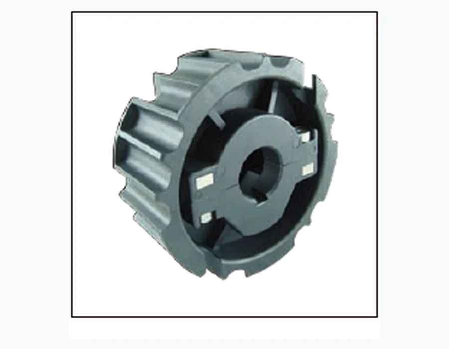
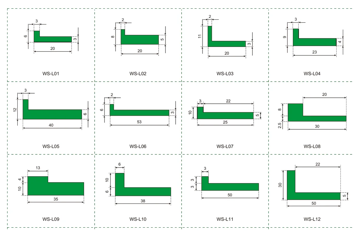
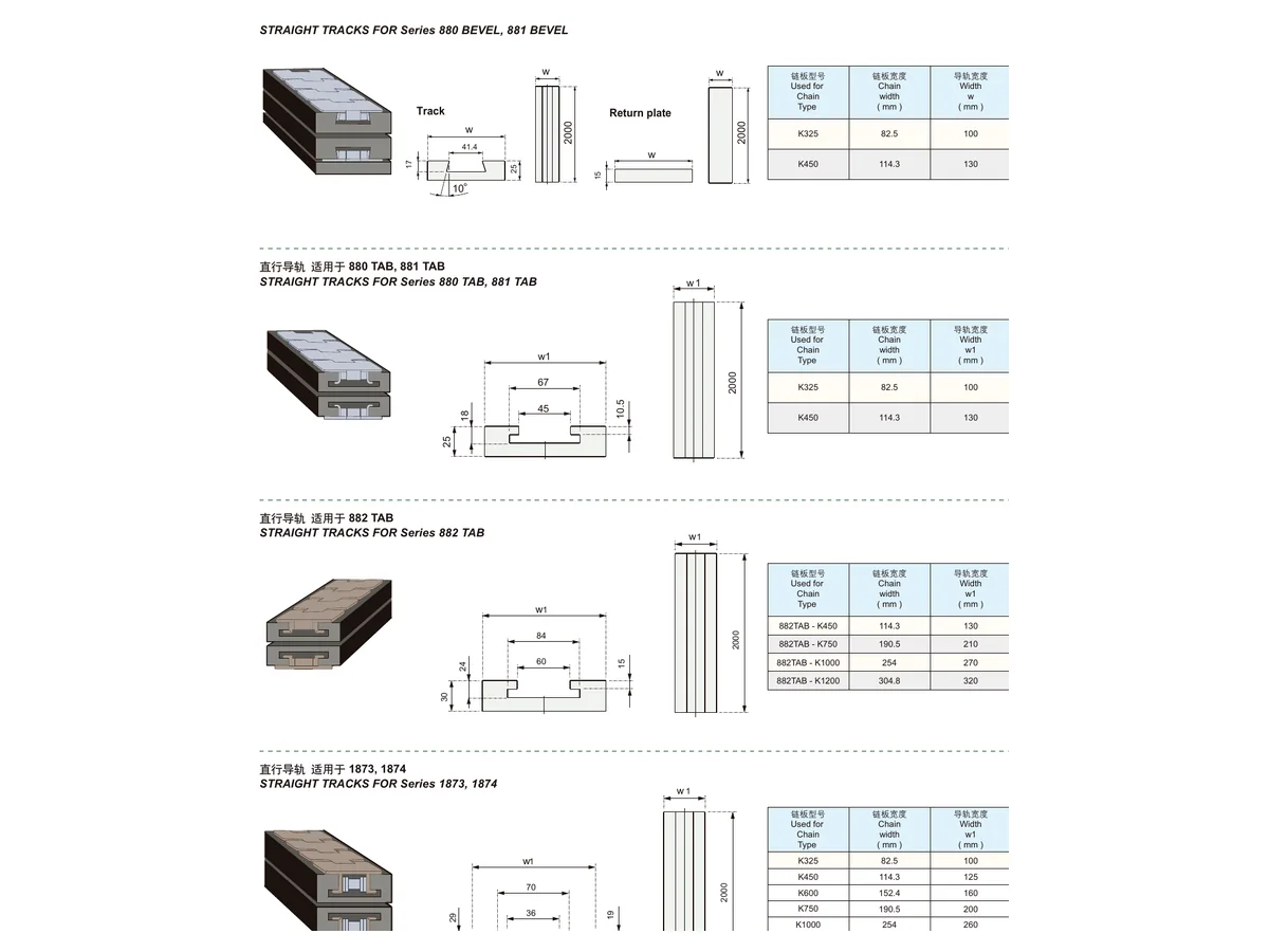
On a modular belts for precision parts transfer conveyor, sprockets, pins, support strips and guide profiles belong in the review whenever they affect the process or refurbishment scope. Pitch is only one drive input; underside geometry and tooth engagement still have to match. Measure wear-strip and guide sections wherever they locate the belt or product.
Check transfer plates, edge guides and wear strips for burrs or step changes that can affect small parts. Photograph any recurring mark or jam location when requesting a replacement or redesign review.
For a new modular belts for precision parts transfer installation, verify belt direction or orientation where applicable, sprocket position and engagement, guide clearance, return support and transfer alignment. For replacement work in this duty, compare the old wear pattern with the surrounding conveyor before assuming the belt itself caused the problem.
| Area | Send |
|---|---|
| Application | Process step and conveyed product |
| Belt geometry | Pitch if known, width, face/open area and overall length/centre distance |
| Conveyor path | Straight/curve, inside radius and transfer points |
| Drive | Sprocket photos/drawing, tooth count, shaft/bore and spacing |
| Duty | Load, speed, wet/dry condition, cleaning and relevant environment |
| Commercial | Quantity, destination, project stage and requested documentation |
It is a useful starting point, but surface pattern, transfer geometry and sprocket interface still matter.
No. Any electrical or antistatic requirement must be explicitly confirmed for the material/configuration.
A simple plan/side view showing part size, conveyor width, transfer gaps and drive/return dimensions is enough to begin.
Send the information already available for the modular belts for precision parts transfer section. A drawing is useful, but a clear photo set plus a few measured dimensions can also start the configuration review.